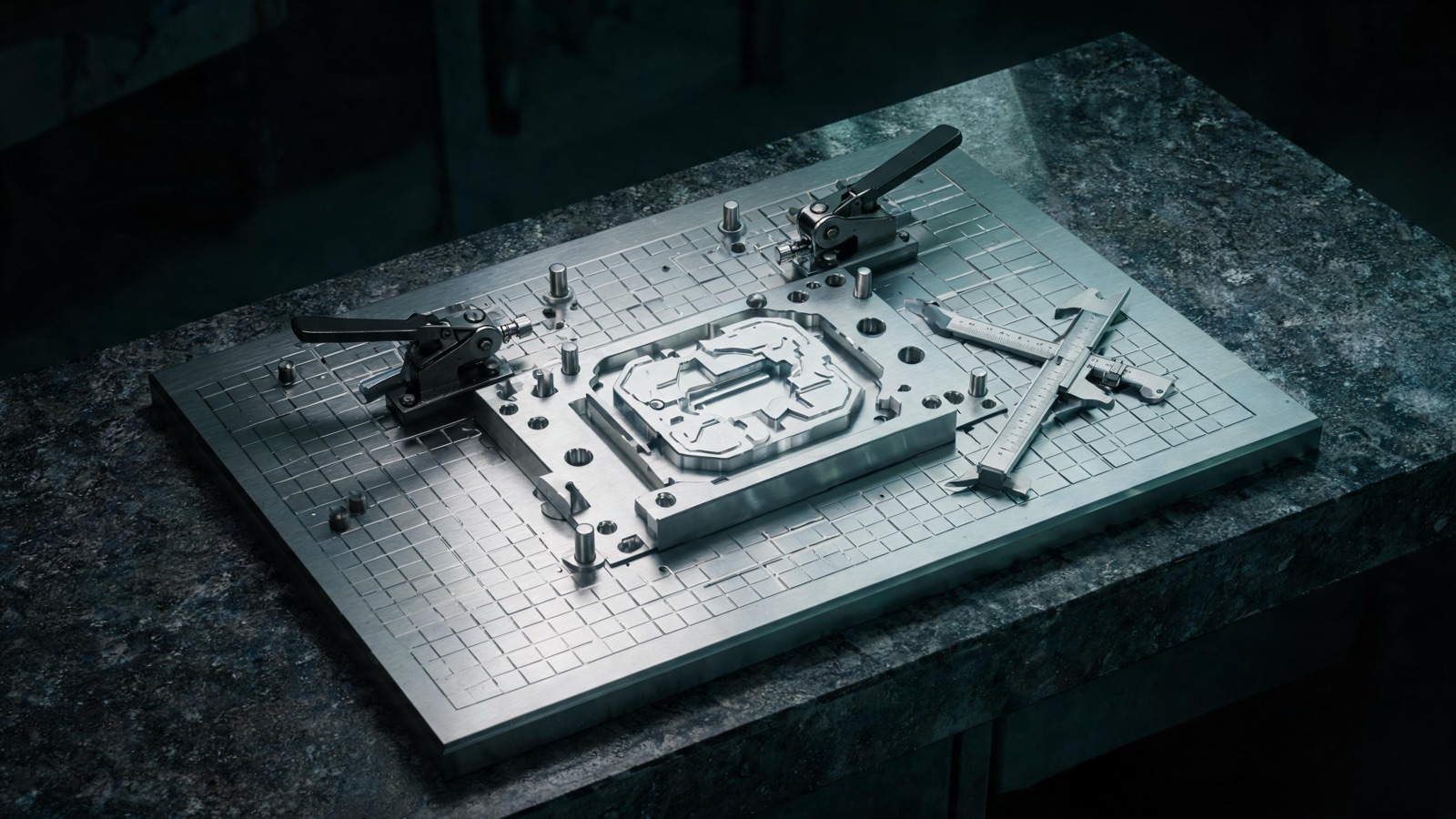
Your best operator locates the part “by feel.” Everyone else on the line gets it a little bit wrong, a little bit differently, every single time. That gap is where your scrap comes from.
It is not a training problem, even though it usually gets treated like one. You can retrain an operator a dozen times and still get inconsistent results if the process depends on human judgment to find the right location. The fix is not more training. It is a fixture that makes the correct location the only location that fits.
Good fixture design takes the skill out of positioning and puts it into the tool. Once that happens, the part goes in the same way every time, no matter who is running the station that day. This guide walks through the location principle behind that idea, how to clamp without distorting the part, what to hand a shop for a quote, and how to keep a fixture accurate once it is running production.
Why “by feel” locating creates scrap
Think about what “by feel” actually means on the floor. An operator eyeballs a scribe line, nudges a part against a stop that is not really a stop, or holds a part steady with one hand while clamping with the other. Every one of those steps has a small amount of variation built in.
Small variation compounds. A part off by half a degree in a weld fixture ends up out of tolerance by the time you stack a few operations together. A part held slightly loose during machining chatters or shifts mid cut. None of these show up as one dramatic failure. They show up as a slow drip of scrap, rework, and “it depends who ran it” answers when a batch comes back inconsistent.
The tell is operator-to-operator variation. If the same print, run by three different people, produces three different outcomes, the process is relying on skill instead of geometry. That is a fixture problem, not a people problem.
The 3-2-1 principle, explained simply
Workholding has a foundational idea behind it called the 3-2-1 principle, and it is simpler than it sounds.
To fully locate a rigid part in space, you need to control six directions of movement. The 3-2-1 method does it with three contact points on one face, two on a second face, and one on a third. Six points, six directions controlled, and the part has exactly one way to sit in the fixture.
Here is the everyday version of the idea. Set a book flat on a table. The tabletop is your first surface: three points of contact stop the book from rocking or dropping through the table, controlling up and down plus tilt in two directions. Now push the book’s spine against a wall, your second surface, two points, stopping it from sliding forward and back or rotating flat on the table. Finally, push the side of the book against a second wall at a right angle, one point, and it cannot slide sideways either. Table, wall, wall, three surfaces, six points, and the book has exactly one place it can be. A fixture just replaces the table and walls with hardened locators sized and placed against your part’s actual datums.
You do not need to run the math yourself to use the idea. Pick your primary locating surface first, usually the largest or most stable face on the part, and rest it on three points. Pick a second surface, ideally perpendicular to the first, and locate it against two points. Pick a third surface for the last point, which locks the part from sliding. Once those six points are in place, the part cannot rock, slide, or rotate into a different position. There is only one physical way for the part to sit, so there is only one way for the operator to load it.
Clamping strategy basics
Locating tells the part where to sit. Clamping holds it there through the operation, and getting it wrong undoes everything the locating scheme accomplished.
Clamp against your locators
The rule that matters most: clamp against your locators, not against open air or an unsupported section of the part. If a clamp pushes the part away from a locating surface instead of into it, the part shifts slightly under clamping force, and the location you so carefully designed stops meaning anything. Every clamp should have a locator, or a solid part of the structure, directly behind where the force lands.
Avoid distortion
Clamping force also has to respect the part itself. Thin walls, castings, or anything with some flex can distort under too much clamp pressure, hold that shape through the operation, then spring back once you release the clamp, leaving a part that measured fine on the fixture and fails inspection off it. Spread clamping force across more contact area, or use lighter clamps in more locations, rather than fewer clamps cranked down hard.
Weld sequence interaction
On weld fixtures, clamp and weld sequence interact more than people expect. Welding introduces heat and shrinkage, and releasing a clamp too early lets the part pull out of position as it cools. Multi-pass welds often need a defined clamping and release order, not just “clamp everything, weld everything, unclamp everything,” to keep distortion from compounding. This is closely related to how end of arm tooling thinks about grip force on a part it did not design.
Designing against the part model
A fixture designed by eye, off a printed drawing or a rough sketch, tends to drift from the actual part over time. Datums get interpreted loosely, tolerances get rounded, and the fixture ends up close instead of correct.
Designing straight from the CAD model fixes that. Locating surfaces, clamp positions, and clearance for tooling access all get built against the exact geometry, not an approximation of it. It also means you catch interference and access problems before you cut metal, instead of discovering them on the shop floor when a clamp cannot physically reach where it needs to.
This matters even more when a fixture serves more than one part in a family. Checking tolerance stack-up across variants before committing to a build lets one fixture handle a range of parts instead of needing a new one for every minor revision.
What to hand a shop for a fixture quote
A vague request gets a vague quote, and usually a design that misses something you assumed was obvious. Gathering a few things before you ask for pricing makes the process faster and the fixture closer to right the first time.
Start with a part model or a physical sample. A current CAD model is best, since it lets the shop design directly against your actual geometry. If a model is not available, a sample part, ideally more than one, lets them capture real dimensions instead of guessing from a drawing.
Next, spell out your tolerance targets, specifically which dimensions actually matter for the downstream operation. Not every dimension on a print needs fixture-level control, and telling a shop which ones do lets them put locating precision where it counts instead of over-building the tool.
Volume matters too. A fixture built for a short run has different priorities, faster to build, less concerned with wear life, than one that needs to hold tolerance across years of daily use. Tell the shop your expected parts per shift and expected fixture lifespan so they size materials and wear surfaces correctly.
Finally, flag any changeover needs up front. If the fixture has to serve a part family, swap between orientations, or integrate with a robotic cell instead of a manual station, that changes the mounting interface and the clamping approach from the ground up. Raising it at quote time, rather than after the design is done, avoids a rebuild.
Poka-yoke: designing out the wrong answer
Poka-yoke is a simple idea: make the wrong way physically impossible, not just discouraged.
A basic example is an asymmetric locating pin. If a part can only be loaded one way because the pin pattern only matches one orientation, the operator cannot load it backward even moving fast or distracted. Another example is a clamp that will not close unless the part is fully seated, so a partially loaded part gets caught before the cycle starts instead of after.
Poka-yoke works because it does not rely on attention or memory. It relies on geometry and mechanism, a meaningfully different kind of reliability than “make sure operators are careful,” because careful is not something you can guarantee shift after shift, especially on a fast cycle or a late one.
Good error proofing usually costs very little extra once you are already building the fixture. It is far cheaper to prevent a misload at the fixture than to catch it in final inspection, or worse, at the customer.
Gauges and validation
A fixture is only as good as your ability to prove it holds tolerance. That is where gauging and validation come in.
Go/no-go gauges are a fast, low-cost way to confirm a part is within spec without a full inspection cycle for every unit. Checking fixtures, built to verify critical dimensions after a part leaves production, catch drift before it becomes a pattern of scrap. First-article inspection against the part model closes the loop: it confirms the fixture is producing what the design intended, not just what looks right on the floor.
A short checklist for validating a new fixture before it runs in full production:
- Confirm all locating surfaces match the datums called out on the part print
- Run a first-article part through full inspection, not a visual check
- Load and unload the fixture with more than one operator to confirm consistency
- Verify clamps fully seat before the cycle can start
- Check for interference with tooling, robot access, or adjacent stations
- Re-check tolerance after a realistic number of load cycles to catch early wear
Fixture care: validation cadence and revision control
A fixture does not stay accurate forever just because it was accurate on day one. Locating pins wear, clamp mechanisms loosen, and repeated loading cycles put real stress on the same handful of contact points, thousands of times over.
Validation cadence
Set a validation cadence based on how hard the fixture runs, not a calendar default. A high volume fixture running multiple shifts a day needs more frequent checks than one used a few times a week. Re-check sooner if parts drift toward one side of your tolerance band, often the first sign of wear before it becomes an outright reject.
Wear items and revision control
Know your wear items ahead of time. Locating pins, bushings, and clamp pads take the most repeated contact and are usually first to show measurable wear. Designing these as replaceable components, rather than machined directly into the fixture body, turns a wear problem into a quick swap instead of a full rebuild.
Revision control matters the moment the part changes. Even a small print revision, a new hole, a tweaked radius, can invalidate a locating scheme that used to be correct. Track which fixture revision matches which part revision, and treat a part change as a trigger to re-check the fixture, not an assumption it will still work.
When a fixture pays for itself
Not every operation needs a dedicated fixture. A one-off part or a very low volume run might not justify the build time. But in most plants, a fixture starts paying for itself once scrap, rework, and inconsistent quality show up regularly on the same operation.
The clearest signal is repeated variation tied to a specific step, especially one that depends on manual alignment or a skilled setup. If that step shows up often in your scrap reports, it is usually cheaper in the long run to design it out with a fixture than to keep managing it with training and inspection.
Common questions
How long does it take to design and build a custom fixture? It depends on part complexity, tolerance requirements, and whether it serves a single part or a family. Simpler single-purpose fixtures move faster than multi-part or multi-station designs. Providing a clean part model and clear tolerance targets up front is the biggest factor in keeping the timeline tight.
Can one fixture handle multiple part variants? Often yes, if the variants share a common locating strategy and differ mainly in size or a secondary feature. Designing against the CAD model of every variant up front, rather than adapting a fixture built for one part, is what makes this reliable instead of a compromise that fits nothing well.
What is the difference between a jig and a fixture? A jig guides a tool, like a drill bushing that directs a bit to the right location. A fixture holds and locates a part for an operation without guiding the tool itself. In practice the terms get used loosely, and many shop tools do a bit of both.
How do I know if my fixture needs to be replaced instead of repaired? If wear is limited to replaceable items like locating pins or clamp pads, repair usually makes sense. If the base structure has worn, been damaged, or the part changed enough that the original locating scheme no longer applies, a rebuild is often more reliable than patching around the problem.
The takeaway
Repeatability is a geometry problem, not a people problem. A fixture built on sound location and clamping principles, checked against poka-yoke thinking, and kept accurate through regular validation turns “however today’s operator does it” into “however the part is designed to be done.” Darioo Industrial designs custom jigs, fixtures, and weld fixtures around the part model from the start, and the same principles apply to end of arm tooling built for the robot that loads them, regardless of who builds the tool for you.